
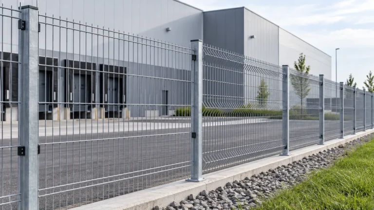
A welded wire fence panel is only one part of a perimeter system. Panel geometry, post spacing, fixings, foundations, gates, corrosion protection and the ground profile must work together. The labels 2D and 3D describe useful construction families, but they do not establish a universal security level or a complete purchase specification.
What buyers mean by 2D and 3D panels
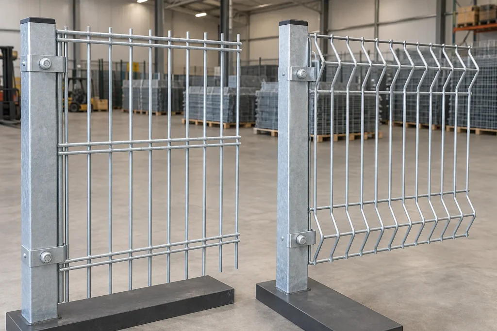
A typical 2D panel is flat and uses paired horizontal wires with single vertical wires. The additional horizontal wire increases stiffness without forming the panel into a corrugated shape. Betafence’s Nylofor 2D product specification is one manufacturer example: its double horizontal wires produce a rigid flat panel. Other suppliers may use different combinations, apertures and names.
A typical 3D panel uses one or more V-shaped horizontal bends. Those formed beams stiffen a panel made from single welded wires and give the face its recognizable profile. Bend count and position usually vary with panel height. Do not confuse a V-bent panel with every product marketed as reinforced or high security; proprietary systems may add strips, closer spacing or specialized fixings.
Choose between the families by system requirements
Flat double-wire panels suit projects that value a clean plane, high rigidity and compatibility with particular accessories. V-bent panels can provide practical stiffness with a different material and price balance. Neither label alone predicts resistance to climbing, cutting, impact or wind. Those properties depend on aperture, wire size, panel height, post and fixing design, installation, and any tested system classification.
For a general boundary, compare visibility, appearance, maintainability and the credible threat. For a controlled facility, ask for the specified security performance and its test basis. A smaller aperture may restrict hand or footholds but also changes wind loading when slats or vegetation are added. Compare the flexible alternative in our chain-link fence guide before deciding that a rigid panel is automatically preferable.
Specify aperture and wire arrangement explicitly
State horizontal and vertical spacing, rectangle orientation, and wire diameters in each direction. For a 2D panel, write the paired-wire arrangement rather than listing only a single diameter. For a 3D panel, state the number and location of reinforcing bends or approve a drawing. Panel width, height, edge overhang and top orientation also belong on that drawing.
Nominal dimensions need agreed tolerances and an inspection method. A thick coating can affect measured outside diameter, so identify whether a value refers to steel core or finished wire. Weld quality, cut ends and local distortion need acceptance criteria appropriate to the project. Our welded wire mesh products guide explains why aperture, wire and finished form should remain linked.
Posts, clips and foundations form the load path
Panel strength is wasted if posts or fixings are underspecified. Record post section, wall thickness, material, finish, cap, centre spacing and attachment method. Fixings should suit intended security and maintenance access. Tamper-resistant hardware may be necessary, but it must still be installable and inspectable. Corners, ends, level changes and gate openings can require different posts.
Foundation design depends on height, soil, wind, terrain, loads added by privacy material and applicable local rules. A supplier’s standard footing sketch is not a substitute for project design where these variables are significant. Tell the designer if screens, signs, climbing plants or electric-fence components may be added later because increasing effective solid area can change loads substantially.
Coating descriptions must cover every component
“Galvanized and powder coated” is incomplete unless coating route, required thickness or mass, colour, pretreatment and repair method are identified. Ask whether wires are coated before welding, the fabricated panel is coated afterward, or another metallic coating is used. Posts, welds, clips, bolts, caps and gates need compatible durability; a complete perimeter should not depend on its least protected fitting.
Colour references should use an agreed system and include permitted variation. Define how cut edges, drilled holes and site damage will be treated. In corrosive or highly visible service, request representative samples and the evidence required by the project specification. Appearance alone cannot confirm zinc coating mass or adhesion.
Plan gates, gradients and interfaces before ordering
A schedule should identify every straight run, corner, change of level, termination and gate. Standard rectangular panels do not automatically follow steep gradients; stepping can create gaps, while raking may need a purpose-made product. Confirm bottom clearance and top line. Underground services, drainage and concrete edges also influence post locations.
Gate leaves, hinges, stops, locks and access controls need compatible clearances and posts. Include emergency egress and accessibility requirements where applicable. At walls or existing fences, detail the termination rather than leave installers to improvise. A site survey tied to a numbered layout prevents quantities being built from perimeter length alone.
Receiving and installation checks
At delivery, compare panel and post labels with the approved schedule, then check dimensions, mesh orientation, wire arrangement, coating condition, straightness and quantities. Separate transit damage from acceptable coating characteristics. Photograph stacked panels before unpacking and quarantine items with crushed edges, broken welds or distorted bends. Use our receiving inspection checklist to connect findings to a shipment lot.
During installation, check post centres, plumb, elevation, foundation cure, clip count and panel clearance. Inspect the complete line from both sides and operate every gate before handover. Record approved repairs and retain spare matching hardware. For supplier comparison, use the departures process in our wire mesh RFQ guide. The result should be an auditable fence system, not a collection of individually acceptable components.